Auke Visser's International Esso Tankers site | home
America's Largest and Most Powerful Diesel- Drive Tanker
Built by Sun for Standard Oil Company of New Jersey, MS Esso Augusta
One of the latest ships to enter the service of the Esso fleet is the new motor tanker Esso Augusta, built for the Standard Oil Company of New Jersey by the Sun Shipbuilding & Dry Dock Company.
The vessel was launched at Chester, Pennsylvania, on June 22 under the sponsorship of Mrs. Edwin S. Hall, whose husband was recently elected a vice president of the Standard Oil Company of New Jersey, and is that company's senior counsel.
On October 2 and 3 the Esso Augusta successfullv passed a series of rigid trials off Cape Henlopen, during which tests she developed a speed of 16 knots at 97 rpm under Force 4 Beaufort Scale weather conditions.
The Esso Augusta is the first of five diesel ships being constructed in accordance with the owners' policy of keeping
abreast of the times in marine engineering developments. The vessel also is the largest Esso ship of this type to be constructed in the United States, and is equipped with the largest Sun-Doxford diesel engine as yet designed and built by the Sun Yard.
The particulars of the Esso Augusta are as follows:
Main Engine
The Sun-Doxford opposed-piston type propulsion diesel is a five-cylinder-in-line engine, with scavenge air pump cylinder between power cylinders numbers three and four. The five power cylinders are 32" in diameter and have a combined stroke of 95". The engine is rated 7,500 bhp at 92 rpm, 8,250 bhp at 95 rpm and 9,375 bhp at 102 rpm.
The welded steel plate bedplate has cross-members arranged to receive spherical cast iron main bearings. The columns, seven in number, are of welded steel, and form A-frames over the main bearings. The frames are tied together to form a unit structure by an entablature which rests on top of and is bolted to the seven frames. The entablature is made in three sections, built ud of steel plates and welded, the three sections being bolted together, and provided with bores to receive the cylinders. Openings in these bores coincide with the cylinder scavenging ports.
The rear columns of the A-frame are girded together by welded steel box sections which serve to support the cast steel crosshead guides, there being three guides for each cylinder, one for the cross-head of the lower piston and two for the crossheads of the upper piston. All of these guides are water cooled.
Cylinders
The cylinders are of usual Sun-Doxford construction, each consisting of a liner, open at both ends, with a water jacket shrunk on the center portion. Near the lower end is a circumferential ring of scavenging ports, so shaped as to give the air a swirling motion as it enters the cylinder. The exhaust ports are located near upper end of liner, so that uni-flow scavenging is obtained. Bores through jacket and liner at the mid-point receive an injection valve and air starting valve on front side and a second injection valve, a relief valve, and a brake valve on back side.
Crankshaft and Pistons The crankshaft is of forged steel, builtup, and consists of five separate sections, one three-crank section for each working cylinder, and one scavenge air pump section, which is located between cylinders three and four.
The working pistons are of cast iron, made in two parts, the skirts being bolted to the rods. The heads have concave
crowns, so that when the pistons meet at end of stroke, the compression space is of approximately spherical shape, and each is provided with five rings of the plain snap type. Each lower piston is attached by a short piston rod to a forged steel crosshead which works in the center guide. Connection to the center cranio is by means of the usual marine-type connecting rod, the length of the rod being 3.82 times the length of the crank throw.
Connection of each upper piston to the crankshaft is by means of a beam attached at its center to the piston and connected at each end to a side crosshead by means of a rod passing down through the cylinder entablature. The two side crossheads are connected to two cranks, one forward and one aft of the center crank, by connecting rods having a length equal to 5.62 times the crank throw. The pistons are fresh water cooled, the inlet and outlet connections being made to the crosshead of lower piston and crossbeam of upper piston by means of swinging arms and
tle.xible rubber tubing.
Braking Arrangement
An interesting feature of the engine is the braking arrangement for stopping the engine quickly when maneuvering.
Mounted in the rear of the engine above the camshaft is a group of valve bo.xes, one for each cylinder, in each of which is a piston valve operated by a cam on the camshaft. The valve bo.xes are in communication with and control the operation of brake valves mounted on each cylinder. The cylinder valves are connected in pairs, each pair being in communication with two cylinders, the cranks of which are 144 degrees apart. The cams are timed so that when the valves are cut in during maneuvering, air is discharged to a diaphragm operating the cylinder valves. Both valves
in the two cylinders whose cranks are 144 degrees apart are opened when the pistons are at the extreme ends of the stroke and the compressed air in one cylinder is allowed to fill the other cylinder in which pistons are at the outer end of the stroke.
Fuel Pressure Pumps
Fuel under constant pressure is supplied to the injection valves by five plunger pumps, assembled in a single unit at
the after end of the engine and driven by gears from the thrust shaft. For maintaining pressure in the fuel lines before
the engine is started, a Watson-Stillman vertical two-plunger pump, driven by a two-horsepower motor, is provided.
The attached crank-driven scavenging pump, characteristic of the Sun-Doxford engines, has a capacity of 28,500 cu. ft./ min.
Safety standards of today require steam drive for tanker cargo pumps, regardless of the propulsion engine. The demand for quick turn-around (which on the Esso Augusta means unloading in 12 hours) requires considerable boiler capacity for the cargo pumps alone, and the steam may also be used to drive other auxiliaries, such as lighting generators, steering engines, various fuel and water pumps. There is also the necessity for cooking, and for seasonal heating of the oil cargo and engine fuel, as well as the ship in general. With the steady increase in size of main engines, the quantity of heat in exhaust gases has risen to a point where its recovery becomes a major factor in the economics of running a motor tanker. Although the temperature of the gases is at a relatively low level, exhaust heat boilers with extended heat-absorbing surface have been developed to such an extent that they can recover the heat
needed to generate sufficient steam at high pressure to drive auxiliary machinery approximately ji lb. of steam per shaft horsepower.
 Exhaust-fired Boiler.
Steam Generating Plant As the result of experience with many other motorships it was decided to make Esso Augusta the first motorship having all of the auxiliaries driven by steam power, either directly or indirectly. As most
of the auxiliaries are electrically operated, the greater part of the steam generated is used to drive turbo-generators.
The steam generating system must be of high flexibility to accomplish this economically.
When the main engine is running at full power, the maxim'um heat is obtainable from the exhaust, but at low ratings, such as while maneuvering or groping through fog, the value of the exhaust is negligible. A waste heat boiler must recover the maximum heat of which it is capable, at all times, but it has to be supplemented by direct-fired boiler equipment to make up any deficiency in steam generation. While in port, of course, the entire steam load must be carried by direct firing.
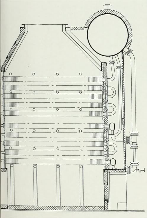
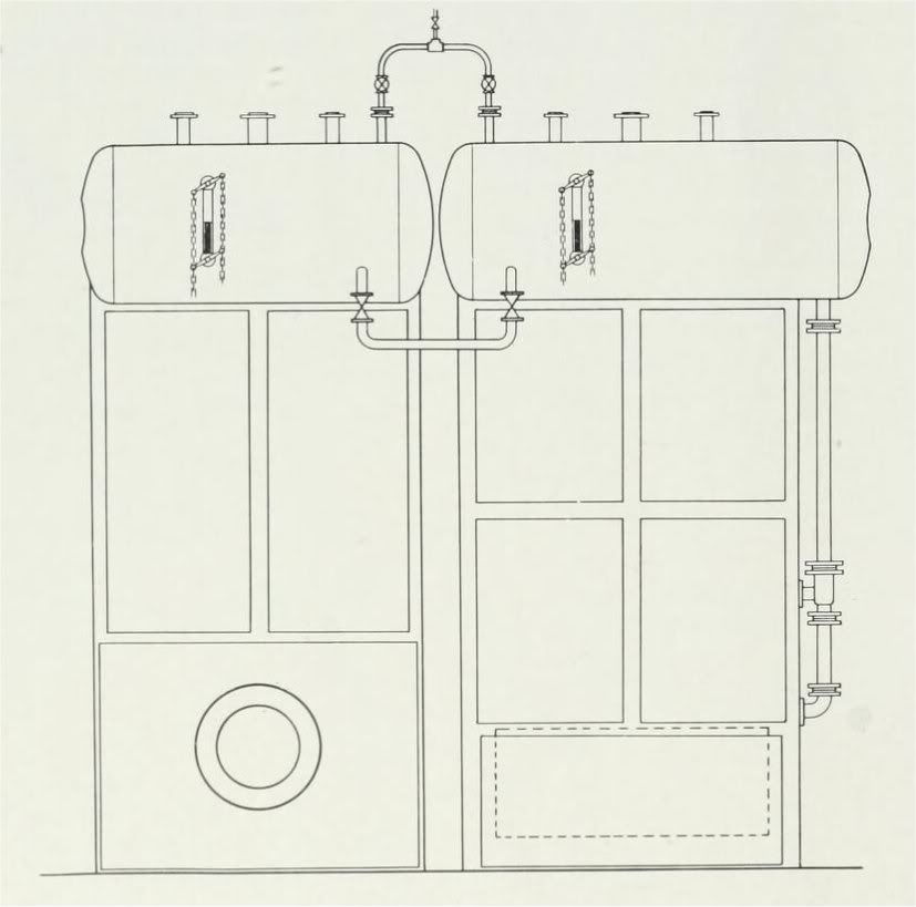
These requirements are fully met by using three steaming units - (1) "waste heat," (2) "stand-by," (3) "cargo." The waste heat boiler is placed just above and slightly aft of the main engine, with connections for receiving all exhaust gases.
Heating tubes are placed horizontally in a chamber through which the exhaust gases pass vertically. The tubes consist of 2" seamless U-bend elements upon which are shrunk a series of cast iron gilled rings providing six times the heat absorbing surface per lineal foot that would be presented by the bare tubing.
Open ends of the tubes are expanded into a tube sheet, to hold them tightly in place, and coupled together by short
U-bends with flanged connections. The return-bend ends of the elements are supported in castings and are free to expand into the surrounding gas-tight chamber. which is heavily insulated to prevent loss of heat.
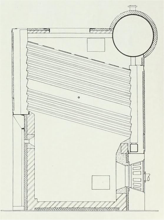
Alongside the waste heat boiler is an independent "stand-by boiler'" of orthodox, direct-fired construction, including
the usual steam drum, straight tubes, and forged-steel sectional headers into which 2" diameter tubes are expanded in groups of four. The furnace is of solid refractory construction, fired from the front by a single oil burner to give a capacity of 8000 lbs. of steam per hour at 200-lb. pressure. No superheater is included in either the waste heat or stand-by boilers.
 Standby Oil fired Boiler.
In order to provide the necessary balance in steam generation between the stand-by and waste heat boilers under varying conditions of tanker service, a General Regulator control system maintains full steam pressure by firing the
stand-by boiler as required to make up any deficiency in output from the waste heat unit. This control has been accomplished effectively by applying a regulating device to the oil burner. The burner is of rotary-cup, atomizer type, having a special ratio cam box to establish and maintain the proper ratio of primary air to fuel oil. Another adjustment sets the vanes regulating admission of secondary air to the burner.
A special limit switch is provided for use, as desired, in controlling the burner operation. It acts at the extreme end of
the regulator travel, at a position corresponding to a steam pressure approximately 5 lbs. per sq. in. above normal.
On reaching this position, relay circuits are opened to shut down the burner. With this system, the burner may be operated over its entire range, corresponding to steam demands from 400 to 8000 lbs. per hr., without manual adjustment or any attention by the operator.
The "cargo" boiler serves the large bulk oil pumps, and consists of a crossdrum, straight tube, forged-steel sectional-header unit having a capacity of 40,000-lb. steam per hour at 200-lb. pressure and superheated 150 degrees. This unit has 5260 sq. ft. of heating surface, composed of 2" boiler tubes, divided into three passes of flue gases by conventional fire brick and cast iron baffles. The setting is heavily insulated and provided with removable panels to give easy access for maintenance or repair. Clean tube surfaces are maintained by four mechanical steam sootblowers placed at the tops of the first, second and third gas passes, and at the bottom of the second and third passes.
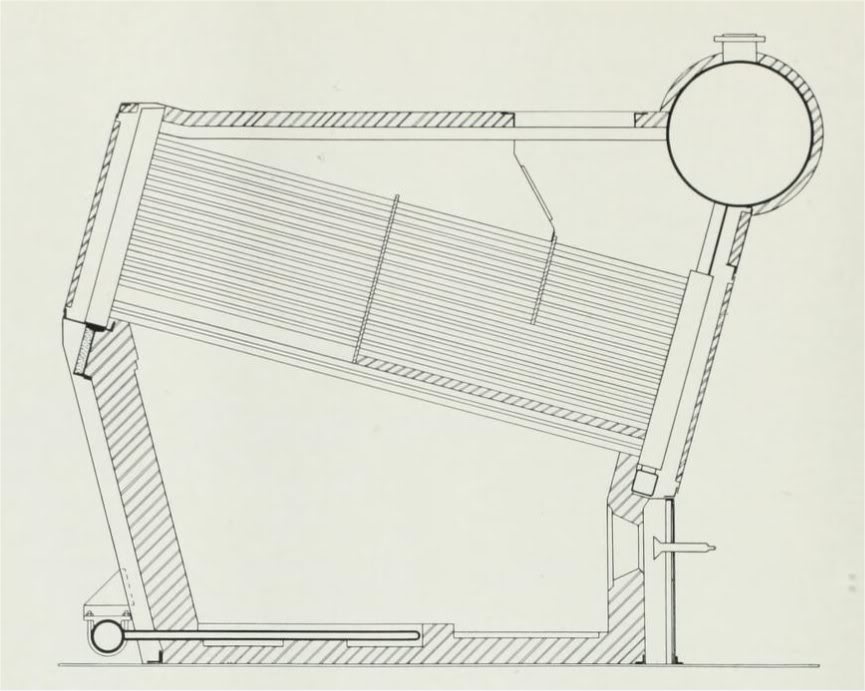 Oil fired Boiler for cargo pumps.
The superheater is of the radiant heat type, arranged for two passes of steam, and consists of series of U-bend elements placed flat on the furnace floor with headers just outside the rear wall at floor level.
Elements extend about half way from the rear toward the front wall, and are similar, in general, to many floor-type radiant superheaters already in tanker service.
 Waste heat and stanby boilers as installed.
By means of these three boilers, the steam demands of the Esso Augusta are adequately met in a way that is unique on diesel-driven ships. Operation of the direct-fired equipment is so coordinated with the waste heat unit that maximum use is made of the surplus heat in the engine exhaust, and operating efficiency is achieved, together with thorough reliat)ilitv under all conditions.
Source : Pacific Marine Review, Volume 38, February, 1941.
|