Auke Visser's International Esso Tankers site | home
First American Arcform Tankers - Part-5
Source : Marine Pacific Review, Volume 33, January, 1936.
Condenser Equipment
The main condenser is of the two-pass, de-aerating type, built by Worthington. It is installed under and takes the exhaust directly from the low pressure turbine cylinder. To take the weight of the turbine casing and to allow for expansion the condenser is mounted on spring supports. Specifications call for a total cooling surface of 3000 square feet, and ability to maintain a vacuum of 28 1/2 inches referred to a 30 inch barometer, and with 70 degrees Fahrenheit temperature of circulating water. The shell is of welded steel plate, the heads of Wompco iron, and the tube sheets of Muntz metal. Tubes are all 70-30 cupro-nickel, 3/4 inch outside diameter, and 18 B.W.G. thickness. These tubes are expanded into the tube sheets at both ends with provision for expansion. At the water inlet head a strainer is installed to prevent foreign matter passing through the tubes.
This condenser is served with circulating sea water by a vertical centrifugal motor driven Worthington pump with a capacity of 4500 to 5000 gallons per minute against head pressures of 7.7 to 11.5 pounds per square inch.
Two auxiliary condensers are installed. Each takes the exhaust from one of the turbines driving the auxiliary generating sets. Each of these condensers is of the same manufacture, materials, and type as the main condenser and must meet the same vacuum conditions.
Reduction Gearing
The main transmission speed reducing gears are of the Sykes Farrel-Birmingham double helical, double reduction type with pinions arranged so that the low pressure unit of the turbines is mounted on top of the condenser. Design of all pinions and gears is such that the maximum tooth pressure will not exceed 66 pounds per inch of face per inch of diameter. The high pressure low speed pinion shaft is extended for driving through a Falk Bibby Flexible Coupling, a 125 kilowatt, 240 volt direct current Diehl generator.
The high pressure spindle of the turbine at full normal load spins 6000 revolutions a minute, and the low pressure spindle 4400 revolutions per minute. These speeds are brought down to 90 revolutions per minute at the propeller shaft by the double reduction gearing. Each turbine spindle connects to its high speed pinion through double Gearflex type flexible coupling.Each high speed gear connects to its low speed pinion through a Falk Bibby flexible coupling. A Kingsbury main thrust bearing of the segmental six shoe marine type, arranged to take thrust in both directions, is installed in the forward end of the low speed gear. This bearing is so proportioned that at maximum power and thrust. pressure will not exceed 300 pounds per square inch.
The line shift is in two sections. each 13 1/2 inches in diameter, of solid forged steel with integral forged couplings, and with diameter increased in way of steady bearings. Tailshaft is 15 1/2 inches diameter solid forged steel and is fitted with a heavy composition liner through the length of the stern tube. A heavy one piece casting of steel forms the stern tube, which has composition bushings at each end, fitted with end grain lignum-vitae bearings of a smooth working fit on the tail shaft liner.
Seventeen feet three inches in diameter, the propeller is n four-bladed, right hand, manganese bronze wheel, cast in one piece and having blades of air foil section and variable pitch with a helicoidal area of 103 square feet. Blades are to be ground and polished and a conical cast iron cap fitted over the propeller nut.
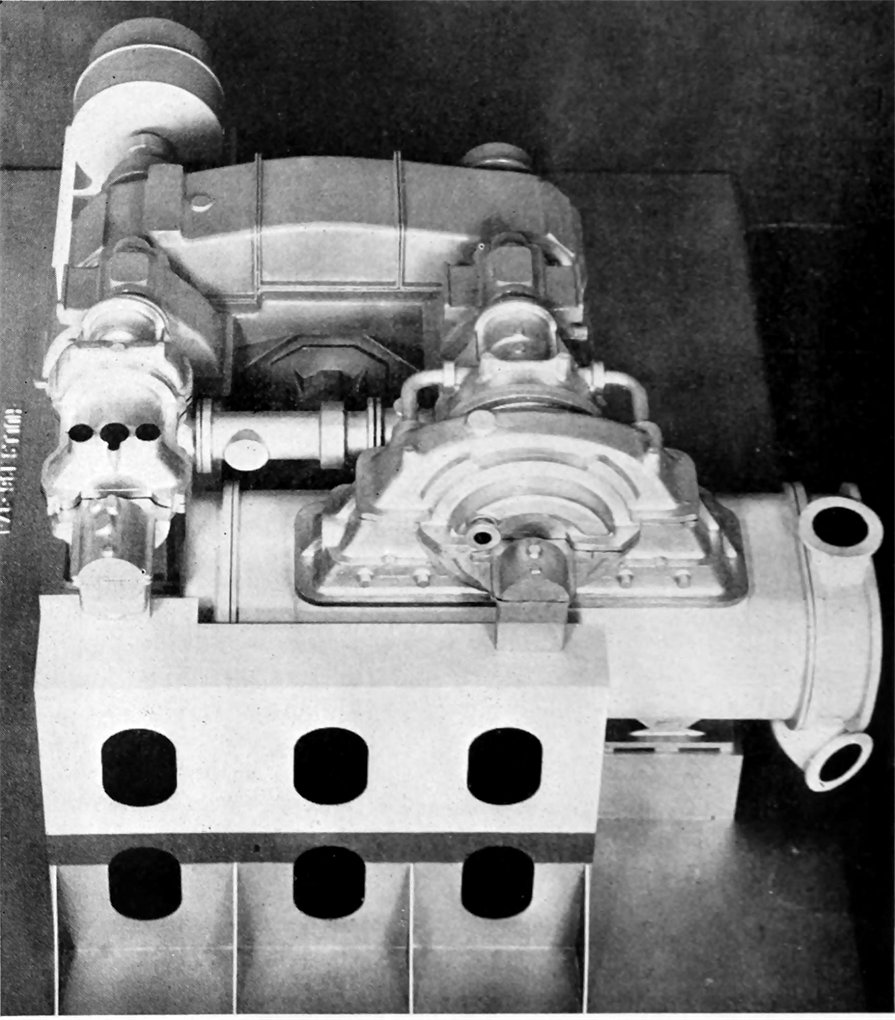 Above: Model to scale showing arrangement of installation of Allis-Chalmers turbine. Farrel-Birmingham gears and Worthington condenser and Diehl generator.
Lubricating Oil System
A pressure type lubricating oil system will serve the main and auxiliary turbine bearings, speed reduction gears and bearings, and main thrust bearings. This system is served by one service pump and one standby pump. That for service is a Northern vertical rotary motor-driven pump with cast iron casing, bronze rotor, steel shaft and bronze glands. It has a capacity of 75 to 105 gallons per minute against a pressure of 40 pounds per square inch.
The standby is a Worthington 6x7x]2 inch vertical simplex steam pump of the same capacity. Two Davis lubricating oil coolers are installed, each with 185 square feet of cooling surface, and capable of handling one-half the maximum capacity of the system. A lubricating oil drain tank of welded construction with 400 gallons capacity at the working level is installed in a dry cofferdam directly
under the main gear case, and is fitted with sump pots for sludge collection, with an air vent to the top of the engine room hatch, and with a float gauge. Two steel storage tanks, each of 600 gallons capacity take care of the service supply of lubricating oil.
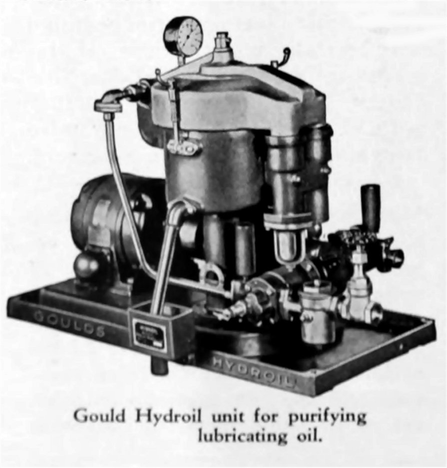 Above: Gould Hydroil unit for purifying lubricating oil.
A motor driven oil purifier of the Gould Hydroil gas-tight type takes care of impurities in the oil. A heater capable of raising 150 gallons of oil per hour from 105 degrees Fahrenheit to 150 degrees Fahrenheit, serves this oil purifier.
Electric Generating Plant.
During normal operation at sea the entire electrical cooking, lighting and auxiliary power load will be carried by the Diehl 125 kilowatt 240 volt direct current generator which drives directly off the high pressure low speed pinion shaft of the main propulsion turbine. This generator is provided with a voltage regulator which maintains practically constant voltage down to 67 per cent of normal propeller speed. When propeller speeds falls to 70 per cent of normal, the electric load is automatically transferred to one of the two units of the auxiliary power plant.
This plant consists of two 200 kilowatt 240 volt direct current Crocker-Wheeler generators, each driven by a De Laval geared turbine. These two generating units are arranged for parallel operation and one of them is kept idling while at sea to take the load when the ship slows down for any reason. Operating conditions for the auxiliary turbines are steam at throttle, 375 pounds per square inch pressure, 725 degrees Fahrenheit temperature, and vacuum 28.25 inches mercury.
Two rotary converters of Electric Specialty Company make are used to change the 230 volt direct current to 60 cycle alternating current at 115 volts for operation of the selsyn-motors that control the engine and docking telegraph systems and the rudder indicator. The capacity of each converter is 1500 volt-amperes at 75 per cent power factor.
Two Crocker-Wheeler 2'40-120 volt balancer sets are installed each of which will take an unbalanced load of 40 amperes.
Lighting and Communication
All lighting circuits are 115 volt direct current. Crews quarters, machinery spaces, and all exposed locations are illuminated by lamps enclosed in water tight fixtures. The cargo pump room illumination will be from lamps in water tight bulk-head fixtures of the swimming pool type with lenses of heat resisting glass. No wiring is allowed in the cargo pump room.
Two floodlights are installed on the foremast and two on the aftermast. One 18-inch Sperry incandescent searchlight is mounted on top of the pilot house with control inside the pilot house.
A five station Henschel telephone system of the selective ringing common talking type connects the pilot house, captain's office, chief engineers room, engine room, and steering engine room.
A Cory selsyn-motor type electric engine telegraph connects the pilot house and the engine room, with a 12-inch double-faced illuminated dial transmitter in the wheel house and a 12-inch indicator in the engine room. The docking telegraph, of the same make and type. has two 12-inch single faced illuminated dial transmitters of the reply type, one mounted on the bridge and one on the deck aft.
Cory also supplied the electric indicators showing both the direction of rotation and the revolutions per minute of the propeller shaft. One of these is mounted at the engine room control platform and the other in the pilot house. An electric rudder angle indicator system of Henchel selsyn-motor type transmits the helm angle from its transmitter in the steering gear room to the indicator in the pilot house.
Wireless Equipment
Tankers R. P. Resor and T. C. McCobb are being equipped by Radio-marine Corporation of America with radio telegraph apparatus far more complete than that usually carried by ordinary tankers and freighters.
These vessels will carry the most modern type vacuum tube radio telegraph transmitters.
Each vessel will have three transmitting sets, thereby covering all the frequency bands generally used in marine service. Model ET-3626C is the type used for intermediate and low frequencies. The Model ET-8002C is a powerful high frequency long range transmitter. In addition to the above two transmitters, a special type of auxiliary transmitter - Model ET-8003 - operating from either the ship's main power supply or a twelve volt storage liattery, will be provided.
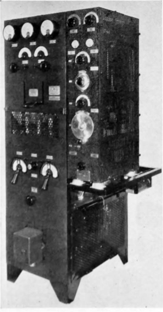 Above: R.C.A. three-unit radio transmitter, covering all frequency bands used in marine service.
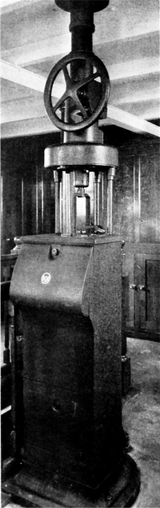 Above: Latest type R.C.A. radio direction finder.
Receivers capable of covering the intermediate, low and high frequencies of the radio telegraph bands will comprise the receiving installalion.
With such equipment, these vessels will be provided with communication facilities such as to enable them to communicate with their home offices, regardless as to distance or location.
In addition to supplying this most complete radio telegraph installation, these vessels are also being fitted with the latest type RCA radio direction finders - Model AR-1445C.
Through the use of this instrument the masters will be able to quickly determine their exact positions by taking bearings on one or more of the numerous beacon stations maintained by the U.S. Government and other leading maritime powers. This precision navigation instrument enables the navigators also to quickly and accurately determine the positions of other vessels.
Through the worldwide facilities of the coastal stations of the Radio-marine Corporation of America, these two vessels will maintain constant and direct communication throughout any voyage which they may be called upon to undertake.
Cargo Pumps and Piping
Three cargo oil pumps of the Northern horizontal rotary type are installed in the pump room located amidships between the two wing fuel oil tanks. and immediately forward of the engine room forward bulkhead. Each of these pumps has a capacity of 1335 gallons per minute against a total pressure of 105 pounds per square inch, and each is driven through a Farrel-Birmingham reduction gear by a Crocker-Wheeler direct current motor. The driving motors are located in the engine room. with shaft extension
through a stuffing box in the bulkhead. Control of mechanism for these motors is located in the deck house over the pump room, with an auxiliary start-stop switch at each motor.
Each pump has four suction connections and four discharge connections: the suction connections are: to a 10-inch line from the sea connecting at each side of the ship; to 12 inch lines from all center tanks; to 8-inch lines from all wing tanks; and to 6-inch stripping lines from all tanks. Discharge connections comprise: 10 inch overboard through the sea suction lilies; l0-inch to all tanks; 8 inch to deck lines; and 10- inchi to deck lines.
To be continued on Part-6
|
See also : First American Arcform Tankers - Part-6