Auke Visser's International Esso Tankers site | home
High Pressure Steam Performance
Source : Pacific Marine Review, Volume 31, July 1934.
High Pressure Steam Performance Standard Shipping Company Tankers S.S. "G. Harrison Smith" and "W. S. Farish" Show Notable Economy in Oil Transport
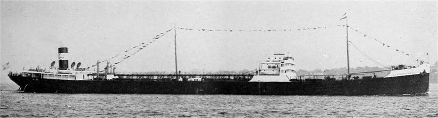 Standard Shipping Company tanker SS "G. Harrison Smith".
In view of the great interest which has been shown in the performance of the 20,615 deadweight ton highpressure steam turbine-propelled tankers which were placed in service by the Standard Shipping Company during the closing months of 1930, it is thought that a comprehensive report upon their performance to date will be welcomed by our readers.
Up to the end of December 31, 1933 the G. Harrison Smith had carried 65 cargoes of crude oil and fuel oil totaling 9,377,016 barrels, and her sister vessel, the W. S. Farish, which was the last to be commissioned, had completed 59 trips totaling 8,451,628
barrels of cargo.
These two tank steamers, having a length between perpendiculars of 525 feet, moulded breadth of 74 feet, moulded depth of 40 feet 6 inches and a summer deadweight of 20,615 tons each, have as propulsive power a DeLaval cross-compound turbine with the high and low pressure turbines in series, connected through flexible couplings to the high speed pinions of the double reduction gears.
The turbine unit develops 4000 S.H.P. when operated at normal rated propeller speed of 75 R.P.M. and under Steam conditions of 375 pounds per square inch gauge nozzle pressure, 725 degrees Fahrenheit total steam heat, and 28 1/4 inches vacuum. The maximum load and speed on the basis of operation under the same steam conditions are 4400 S.H.P. and 77.5 R.P.M. propeller
speed. The astern element is mounted in the forward end of the low pressure turbine casing, with full steam flow the astern turbine is capable of exerting a torque equal to about 89',; of the full ahead torque, and the revolutions reduce momentarily to about 37.5 upon reversal.
In an emergency either turbine can be operated alone on high pressure steam with the other disconnected.
The high pressure turbine is of the impulse type and has 11 pressure stages, each of which is formed by a set of stationary nozzles (set in a diaphragm) and one, or two rows of rotating buckets. The first stage of expansion is effected through two wheels and one diaphragm with a drop of 125 pounds in pressure through the stage. The remaining impulse stages are on single wheels with expansion diaphragms between. The speed of the high pressure turbine at normal load is 5,480 R.P.M. The low pressure turbine, which is of the same type as the high pressure turbine, has 7 stages of expansion and contains both ahead and astern elem which are separated by a common exhaust chamber.
The astern turbine has 2 stages of expansion made up of 2 rows of rotating buckets separated by a single row of stationary guide vanes in the first stage and one row of rotating buckets and one expansion diaphragm in the second stage.
The rotor of the L.P. turbine is of the built-up type.
The ahead and astern rotor assemblies are rigidly held together by carefully fitted heat-treated, highgrade steel bolts passing through the adjoining sections.
The speed of the L.P. turbine at normal load is 4,270 R.P.M.
Each turbine shaft is connected to its respective high speed pinion shaft by means of a DeLaval flexible coupling of the claw type. Each high speed pinion drives a high speed gear having a shaft connected to the shaft of the low speed pinion; the 2 low speed
pinions drive the low speed gear, whose shaft is rigidly connected to the propeller shaft.
Steam is supplied by two Babcock and Wilcox straight tube boilers at 420 pounds per square inch working pressure and a total steam temperature at the superheater outlet of 750 degrees Fahrenheit. Each boiler has 5,080 square feet of heating surface, 903 square feet of superheating surface and 3,460 square feet of air heating surface. The superheaters are of the interdeck type, extending the full width of the boilers and mounted above the fifth row of generating tubes in the first pass of the tube nest. The tubes in the last pass are made of a high heat resisting chrome nickel steel alloy. The drums are fitted with an internal desuperheater.
All steam generated passes through the superheater and only such quantity as is required passes automatically through the desuperheater providing saturated steam for the steam auxiliaries.
Each boiler is fitted with four Todd forced-draft oilburning fronts with mechanical pressure atomizing burners, in association with the balanced draft system.
Under normal sea operating conditions, all electric power for auxiliaries and lighting is supplied by a sea service generator which is connected to the starboard low speed pinion of the main unit. If the speed of the main turbine propelling unit is reduced to a point unsuited to the operation of this generator, the stop valve of one of the auxiliary turbo-generators is automatically opened, and the electrical load taken up by this unit. The main condenser is hung athwartship underneath the low pressure and astern turbine and mounted on 2 pedestals fitted with counter-balance spring to allow for expansion. The condenser is the first of its type to be used in the merchant service, having tubes rolled at both ends.
There are four feed water heating units in series, viz: first stage heater, after condenser, second stage heater and third stage heater all mounted on the forward engine room bulkhead.
The three stage heaters receive steam bled from the main turbines and, therefore, relieve the main condenser of the duty of condensing this steam, so that a smaller condenser can be used and less water need be circulated through it. However, the outstanding fact about the extraction heaters is that the heat which they absorb in condensing the steam is all returned to the
boiler instead of going overboard in the condenser circulating water. The heat thus returned to the boiler represents a large percentage of the heat which was in the same steam when it was received at the turbine throttle, so that the efficiency of the turbine in converting heat into work, so far as this steam is concerned, is exactly 100 per cent, as against in the neighborhood of 20 per cent for the steam which is condensed in the condenser. The use of three stages of bleeder extraction heaters, also known as the regenerative feed heating cycle, should reduce the fuel consumption of the power plant by some 8 per cent.
These two vessels have been employed in the crude oil trade from the Gulf to ports north of Hatteras.
However, the SS W. S. Farish made one voyage from California with fuel oil. On the Pacific Ocean leg of this voyage her observed steaming distance was 2971 nautical miles on a total consumption of 2012 barrels of fuel oil, at an average speed of 10.27 knots. Average steam pressures were 410 lbs. at the boiler, 400 lbs. at the main throttle, 390 lbs. at high pressure nozzle, 10 lbs. at low pressure nozzle, and 28.1 vacuum. Steam temperature was 755 degrees Fahrenheit at the boiler and 725 degrees Fahrenheit at the throttle.
We also show a summary covering the performance of the W. S. Farish and G. Harrison Smith for the past three years, which indicates the superiority of high pressure steam turbine installations as compared to steam reciprocating propelling units. The pounds of fuel per thousand ton miles of cargo carried during three years has been determined by dividing the total pounds of fuel consumed by the product of the average cargo carried per loaded voyage and the total miles transited figuring in all cases from sea buoy to sea buoy. It is believed that this figure is of interest and value in the practical analysis of tanker operation, having regard to long voyages and to the peculiar navigating and cargo conditions under which many of such vessels operate in the various trades.
In common with all other tankers of the Standard Oil Company (New Jersey) interests, these vessels are equipped with the most modern safety appliances, crew conveniences and with the very successful Butterworth System of tank cleaning.
Summarv of Performance Data 1931-1932-1933
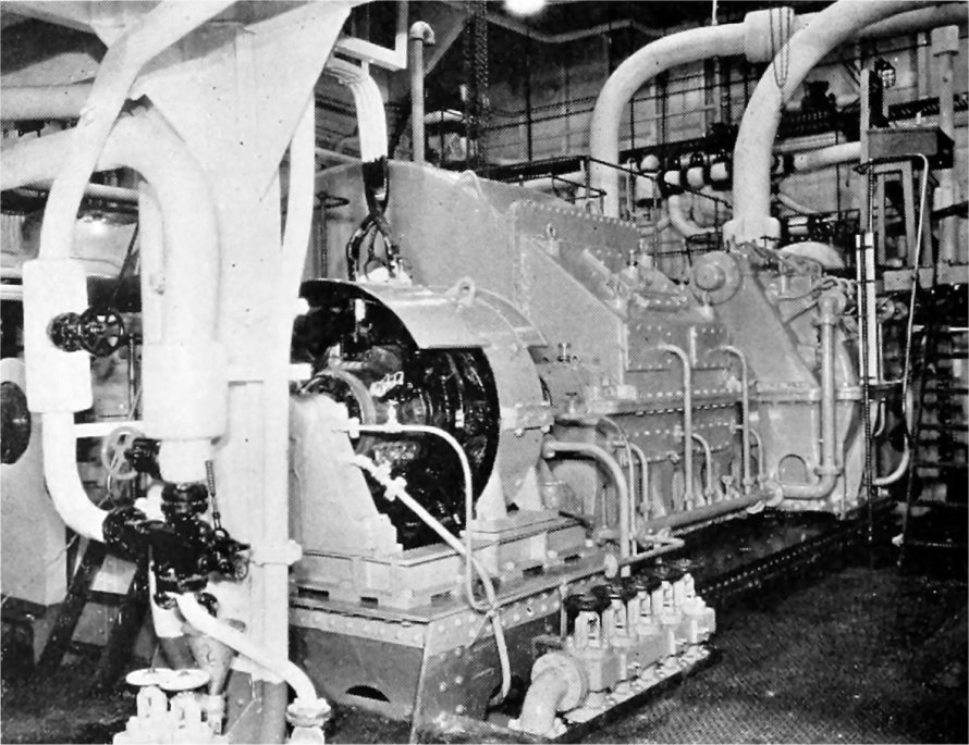 Starboard side of engine room on tanker G. Harrison Smith featuring De Laval gear case and turbine with generator driven off low speed pinion shaft.
|