Auke Visser's MOBIL Tankers & Tugs Site | home
The Tug "Magnolia", Another Diesel-Electric Installation
LATEST addition to the fleet of the Magnolia Petroleum Company of Beaumont, Texas, is the new diesel-electric tug Magnolia, built for canal, harbor, and coastwise service, with headquarters in Beaumont. Built by Levingston Shipbuilding Company, Orange. Texas, the vessel is 100 feet long, 26 feet in breadth and has a depth of 12.5 feet. She is of all-steel construction.
Power for main propulsion is supplied by a 12-cylinder, 2-cycle General Motors Model 12-278A diesel engine, rated 1200 hp. at
750 r.p.m.. and direct-connected to an 814-kw., 560-volt, d.c. generator, which supplies current to a 1020- hp., 560-volt, d.c., 700 - 875 r.p.m. propulsion motor. The motor is directly connected to the high-speed pinion shaft of a reduction gear.
The propeller shafting is connected to the reduction gear by a special Coupling manufactured by Levingston Shipbuilding Company and approved by the American Bureau of Shipping, and the motor, reduction gear and shafting are capable of delivering over 1000 s.hp. at 160-200 r.p.m. to the three-blade, 8'10-diameter by 7'-pitch screw propeller.
The propulsion generator is constructed with an exciter rated at 24 kw., 120 volts, d.c., 375-750 r.p.m. The idle exciter, when not in use for providing excitation to the propulsion generators and propulsion motor, is available for supplying power to the distribution board for general ship's service. This 24-kw. power which is available when the vessel is underway is ample to provide for the normal use of electricity for the steering gear, ventilation system, refrigeration, heating and lighting. On long trips, this amounts to a considerable saving in the use of machinery.
The motor speed and, correspondingly the propeller and ship's speed, can be controlled from any one of three Stationsthe pilot house, the engine room or the afterdeck conning station. When under heavy tow, the motors can be operated at reduced speed, but at full voltage, full power and full engine speed, by increasing the field current to a value which will allow maximum armature current without overload. The motor fields are protected against overheating at stalling condition by a field reducing contactor. A current-limiting device, which regulates the generator field current, is provided to limit the current in the propulsion loop to 125 % of full load value, and to protect the electrical machines against momentary excessive current caused by rapid acceleration and reversing.
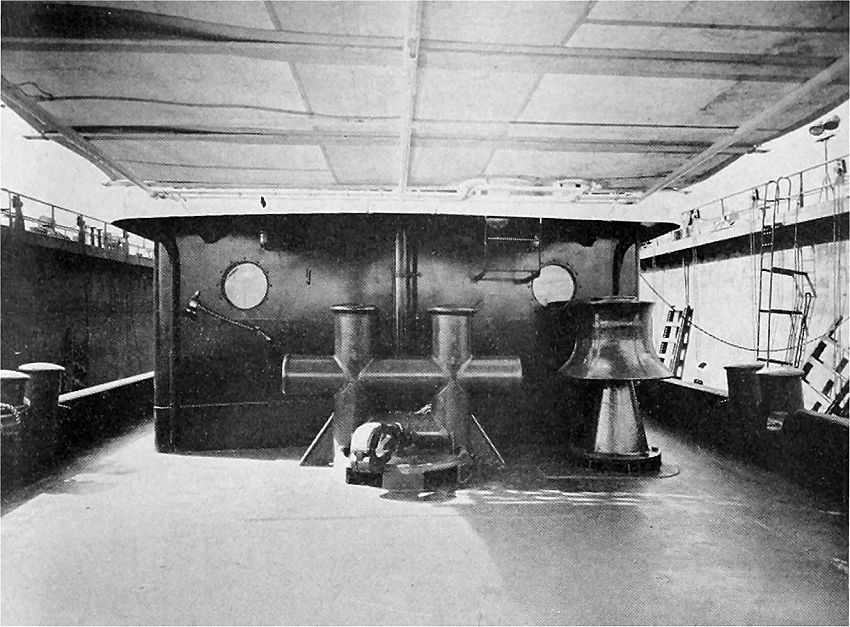 Aft of deck house, showing towing bits; towing hook in immediafe foreground; and to the right on the starboard side, the gypsy.
The diesel-electric propulsion system gives the pilot finger-tip control at any speed ahead or astern and allows for the full development of power when running light or with heavy tow. Under heavy tow, full power is developed at slower propeller speeds, eliminating slip.
The electro-hydraulic steering gear employs as a prime mover a 10-hp. non-reversing electric motor, driving a variable-stroke reversible pump. The liquid handled by the pump actuates the single opposed rams. The pilot house equipment consists of a polished brass column, on which is mounted the rudder indicator and a 48-diameter polished brass steering wheel. The starting and stopping push buttons to control the steering-gear motor are installed in the pilot house, which allows full control of the steering
gear from the pilot house, independent of the engine room. A pilot light is installed in the pilot house to show the wheelman that the
steering gear is running. The vessel can be steered from either one of two stationsthe steering station in the pilot house, or the conning station on the after boat deck.
The principal items of auxiliary machinery are two diesel-driven 50-kw. electric generators, a fire pump, bilge pump, lube oil stand by pump, fuel oil transfer pump, air compressor, and a motor generator set.
The two 30-kw. auxiliary diesel-driven generator sets are duplicates, each being driven by a 45-hp. General Motors Model 3-71 diesel engine, direct-connected to a 30-kw. compound-wound 120-125-volt generator. One is installed on the port side and the other on the starboard side of the engine room. The units are self-starting and equipped with battery chargers for recharging
their own batteries.
The fire pump has a capacity of 360 gallons per minute at 125 pounds pressure. It is direct-connected to a 30-hp. electric motor. For lighting fires, there is an outlet on each side of the vessel's house, and there is a fire monitor installed atop the captain's cabin.
The bilge pump, lube oil standby pump, and fuel oil transfer pump are all positive displacement pumps.
The three pumps are exact duplicates, thereby eliminating the necessity for carrying large quantities of spares. The bilge pump is driven by a 7 1/2-hp. motor; the lube oil standby pump by a 5-hp. motor; and the fuel oil transfer pump by a 3-hp. motor. The air compressor, driven by a 5-hp. electric motor, is equipped with automatic controls and air is stored in a 20" x 72" air receiver. Compressed air is used for blowing the vessel's whistle and for cleaning in the engine room.
A motor generator set is installed so that the vessel can be laid up in its own home port where electricity frorn the dock is available. By plugging in the motor generator set from the shore connection to power on shore, the vessel's lights, fan, refrigeration and heating can be operated without running the diesel-driven generators installed on the vessel. The motor generator set is equipped with a 7 1/2-hp. motor driving a 5-kw. generator.
The engine room, all quarters and the galley on the main deck have forced ventilation. Two large blowers blow air into the after end of the engine room and under the engine room floor plates. Exhaust is up through the vessel's stack. Air is blown into the galley and into the quarters through metal ducts, allowing for a complete change of air in less than two minutes.
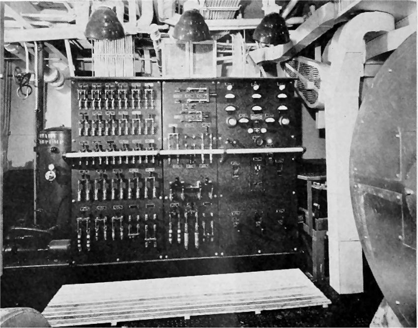
 Engine control slation in engine room.
In addition to forced ventilation, each room is equipped with an oscillating electric fan. A larger oscillating electric fan is installed in the galley.
For heating the vessel, a boiler is installed in the engine room. The boiler is complete with fuel pump, blowers, motors, transformers, low-water cutoff and pressure switch, to make the boiler operation entirely automatic. Convector-type radiators are installed in each room and a large radiator is installed in the stowage space, which is forward below the main deck.
The lower, or deck, house is constructed of welded steel. All outside doors dog watertight on rubber gaskets. Each inside door has a louver in the bottom half to assist the ventilating system.
There are two rooms forward, each equipped for two men. The galley is next aft. Next after the galley is the upper engine room.
On the starboard side of the upper engine room there is a toilet room forward and a toilet room aft. On the port side of the engine room aft is the mate's room. At the extreme aft end of the house are the chief engineers room and a second room equipped for two men.
The galley extends entirely across the house. It is equipped with large stainless steel sinks and drainboards with storage space below. The range is equipped with a carburetor burner. Built into the galley is a large double-door refrigerator, complete with two stainless steel service doors. Seven persons can be seated at the mess table. A 20-cu. ft. stainless steel frozen food locker with a lift top is part of the galley equipment, but is installed in the storage space below the main deck forward. There are also installed in the same space, a linen locker built of wood and a galley-stores locker built of steel.
There is a raised pilot house forward on boat deck with captain's quarters immediately aft. The pilot house is fitted with seven windows, a door on either side opening upon a small bridge leading to the edge of the vessel, and another door leading to the captain's quarters. In bad weather the partable glass in the pilot house windows can be opened a few inches just in line with the
pilot's vision by raising the top section of the glass and lowering the bottom section. In the pilot house are installed a magnetic compass in its binnacle, the engine controls, steering stand and steering wheel, ship-to-shore telephone, engineer. p.m. indicators, tell-tale panel, motor control and tell-tale light for the steering gear motor, barometer, clock, whistle pulls, speaking tube, bell and jingle pulls, and resound from the engine room gong. In the after end are two fixed plate-glass windows which enable the pilot to look aft. The vessel's stack is sharply elliptical so the pilot's view will not be obstructed.
The captain's cabin, just aft of the pilot house, is equipped with a mahogany berth with drawers beneath, a large built-in mahogany clothes locker, a desk and an upholstered settee. The doors in the captain's quarters are of teak. Alarm bells are fitted in all quartets.
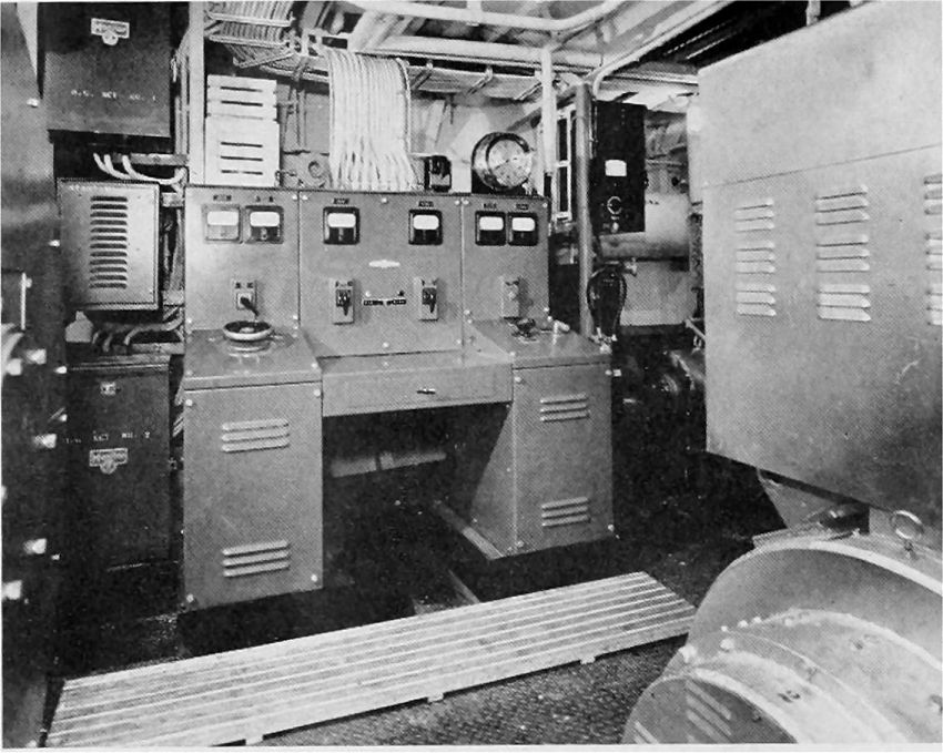
 Engine room view, showing distribution panel for ship's service.
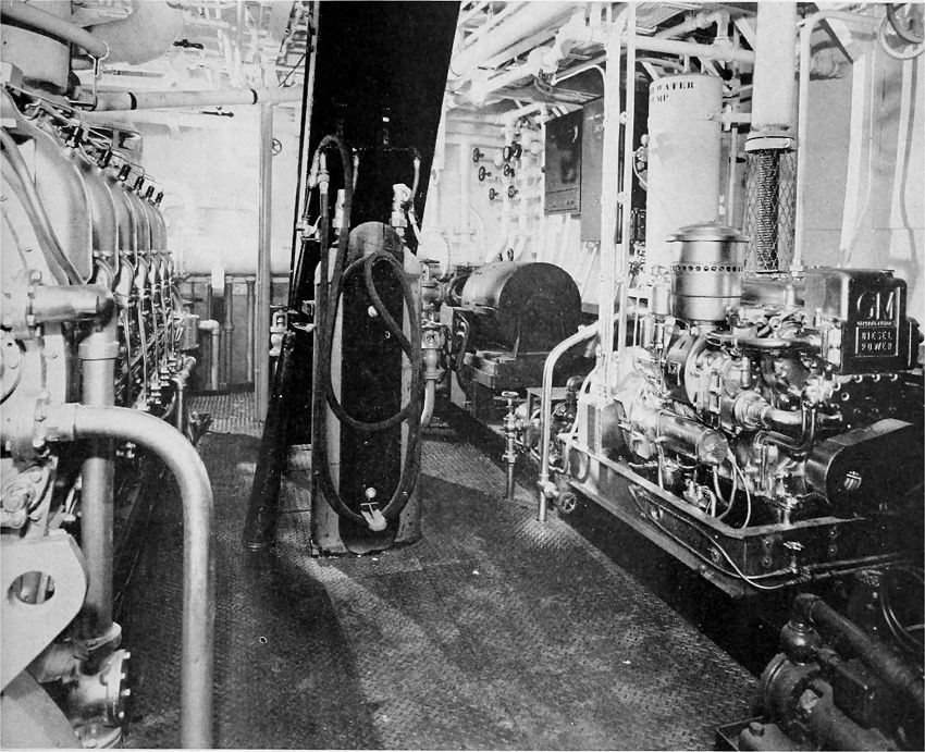 Looking forward from engine room, showing on the left lhe main propulsion engine, and in the right foreground the
auxiliary generating set; on the right the scavenging pump and in the direct cenler two CO2 bottles for fire fighting.
CO2 fire-fighting equipment installed on the vessel includes two 50-lb. cylinders installed in the engine room with 25 feet of hose and discharge nozzle. Throughout the vessel there are installed five 15-lb. CO2 portable hand extinguishers on marine brackets.
The vessel is equipped with a 16-ft. lifeboat. In the lifeboat are all the supplies required for coastwise service. The vessel has life preser\ers installed in racks in each of the rooms. and it is equipped with four 30 U. S. Coast Guard approved ring buoys and two electric water lights.
The Magnolia's keel was laid on October 5, 1949 she was launched on January 18, 1950. The trial trip was run on March 22, 1950. The "Flying Red Horse" mounted on the enameled insignia gallops forward on both sides of the ellipticalstack.
|
Source : Pacific Marine Review, Volume 47, July 1950.