GAS-Carriers E - H > 50,000 CBM ( Part - 2 )
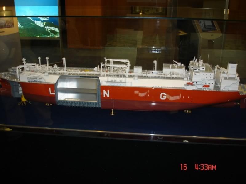
Exmar Regasification vessel ( LNGRV )
"Exmar".
( Photo Copyright Geir Wiggen )
"Exmar".
( Photo Copyright Geir Wiggen )
Publication from EXMAR, Belgium.
The Exmar Regasification Vessel
As an alternative to the expansion of onshore LNG import terminals, Exmar has been instrumental in developing the Energy
Bridge TM vessel (LNGRV) for the American energy trading company Excelerate Energy. This is an innovative design allowing the vessel to regasify the LNG on board and discharge the high pressure gas directly into the consumer grid system, through a dedicated mooring arrangement and subsea high pressure pipeline thus bypassing the need for an onshore LNG import terminal. This vessel, however, remains fully compatible with conventional land-based terminals.
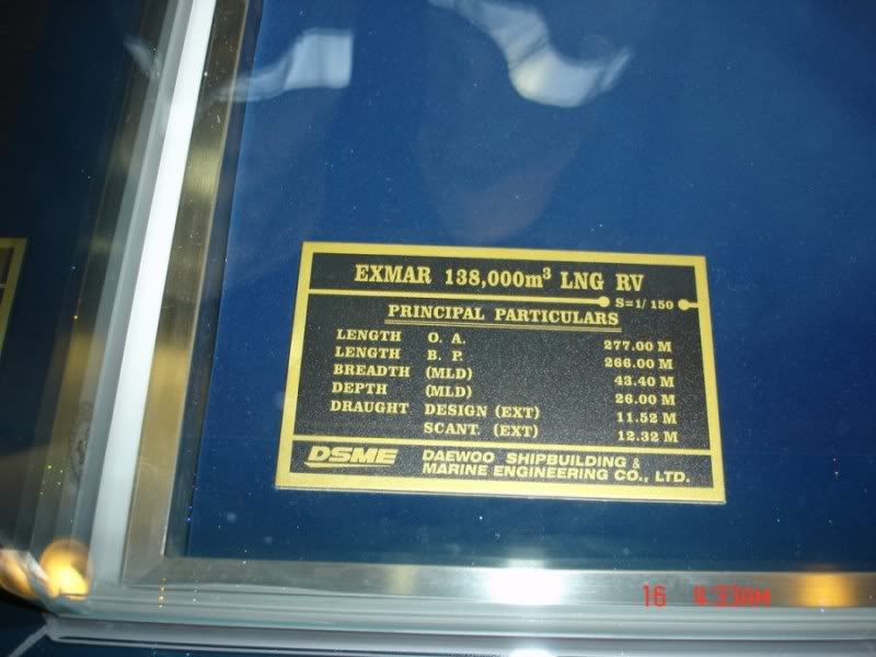
The first vessel, EXCELSIOR with a capacity of 138,000 m3, was delivered in January 2005 from Daewoo Shipbuilding and
Marine Engineering in Korea, a leading shipyard in the construction of the latest generation of LNG carriers. An additional vessel, EXCELLENCE, was delivered in April 2005 followed by EXCELERATE in October 2006. The first of a series of enlarged (150,900m?) LNGRVs named EXPLORER was delivered in April 2008. A further four are under construction for delivery in April 2009 (EXPRESS), September 2009 (EXQUISITE), November 2009 (EXPEDIENT) and June 2010 (EXEMPLAR).
Gulf Gateway, as it was named, is the first offshore LNG regasification terminal in the world. The buoy was installed in
the Gulf of Mexico and became operational in March 2005. It is located about 116 miles offshore Louisiana and capable of
delivering baseload gas volumes in excess of 500 million cubic feet per day. The second terminal, Northeast Gateway, is located about 13 miles off the coast near Boston and has been operational since early 2008 with a capacity to deliver up to 800 million cubic feet per day.
Regasification System
The regasification system is based on proven land-based technology and has been selected to minimise the impact on the existing cargo systems and the vessel's ability to trade as a conventional LNG carrier. LNG is supplied from the cargo tanks to the regasification plant by feed pumps arranged in a dedicated well within the tanks. Removal of these pumps is possible even with the cargo on board.
The regasification plant is arranged on the upper deck forward of the cargo tanks and consists of 6 independent trains each having a high pressure LNG pump and a shell and tube type vapouriser with a design capacity of 100 million standard cubic feet per day (MMscfd) bringing the total design capacity to 600MMscfd at a discharge pressure of up to 100 bar. Discharging is completed in about 5 days.
The heating medium for the vapourisers is seawater or freshwater, with or without steam heating as required by the prevailing environmental conditions.
Two different means of shore connection are provided. The first is through a submerged buoy connection arranged in a dedicated room located forward of the cargo tank area, and a subsea flexible riser. The second is through a conventional high pressure shipside manifold featuring ANSI 900# flanges arranged amidships.
A metering station is provided for the commercial evaluation of the quantities of gas being transferred.
STL Mooring System
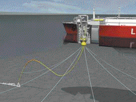 The LNGRV is moored on a Submerged Turret Mooring and Offloading system developed by APL in Norway. This system has an extensive track record on crude oil shuttle tankers in the North Sea and consists of a buoy moored to the seabed which is pulled into and secured in a mating cone in the bottom of the vessel thus connecting the mooring system. Inside the buoy is the turret with connection to the mooring and riser systems. The outer buoy hull can rotate freely with the vessel around the turret by means of internal turret bearings. Gas is transferred through a swivel to the piping system of the vessel. When disconnected, the buoy floats in an equilibrium position with a pickup line to the surface, ready for new connection.
The system was developed further in 2008 when EXCELSIOR was located alongside a berth in Bahia Blanca, Argentine during the winter period and supplied on a regular basis by ship-to-ship (STS) transfer from conventional LNG vessels. At the same time EXCELSIOR was regasifying and supplying natural gas at ambient temperature via the conventional high pres-sure shipside manifold to local industry and the national grid system.
PRINCIPAL PARTICULARS
Main dimensions
Length Overall 291.0 m
Length between Perpendiculars 280.0 m
Breadth, moulded 43.4 m
Depth, moulded 26.0 m
Designed Draft, moulded 11.6 m
Capacities
Cargo Tanks (100% @ -163 degrees C) 150,900 m3
Maximum Cargo Intake (98.5% filled) 148,620 m3
Water Ballast Tanks including peak tanks 53,000 m3
Heavy Fuel Oil Tanks 5,700 m3
Deadweight @ Designed Draft 74,000 mt
Complement 40 Persons
Propulsion
Main Propulsion Main Steam Turbine
Maximum Power (MCR) 36,000 SHP @ 88 RPM
Service Power (NCR) 32,400 SHP @ 85 RPM
Service Speed 19.1
|