Auke Visser's International Esso Tankers site | home
THE GIANT TANKERS - ( Newbuilding program in the 50's )
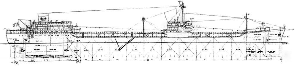
Profile of fhe New 26,000 D.W.T. Tankers Now Under Construction.
THE GIANT TANKERS
The sudden emergence of the giant tanker construction program as the major ship construction news of the year
has aroused great interest on the part of the oil companies' shipyard operators, tanker officers and crews, and the Maritime industry as a whole.
There are several sizes currently being built or planned with a possibility of even greater size for the near future.
The 26,000-ton and 28,000-ton sizes have reached a point where plans and specifications are being released and they will appear from time to time in the PACIFIC MARINE REVIEW. A proposed 30,000 ton ship has not passed the discussion stage. The length varies somewhat at around 620 feet and the beam around 84 feet.
In the planning of these ships the use of the experimental towing tank has played a new and important part. The
Stevens Institute tank was used for the vessels of the Standard Oil Company of New Jersey and Gulf Oil and five models were required in the tests to determine which of several bow designs was the most efficient. Towing tank and model basin technique is being found well worthwhile for even very small vessels including tugs and barges.
Sun Shipbuilding and Dry Dock Company, which is having an important part in the construction program, had to reconstruct its shipways on the land side in order to accommodate the great length of the tankers.
Contracts for the construction of six new 26,000 D.W.T. tankers, having a carrying capacity of 228,000 barrels of high gravity cargo, have been signed by Standard Oil Company ( New Jersey), two of the ships to be built by Sun Shipbuilding & Dry Dock Company, Chester, Penna., and four by Newport News shipbuilding and Dry Dock Com-pany, Newport News, Va. The vessels will be built from designs prepared by the Marine Department's technical staff. Each ship will have a normal complement of about 50 officers and men.
Dimensions and Particulars :
The vessel will have a rounded curved stem, a merchant cruiser stern, a vertical mast for radar and radio antennae and a raked streamlined stack. The propelling machinery spaces will be located aft, consisting of engine room and boiler room, separated by a watertight bulkhead. The boiler room will be on a raised flat aft of the engine room. The hull will be of the single deck design, with forecastle, poop, and bridge deckhouse, all connected together by the usual fore and aft walkways at the center of the vessel. The upper deck will be the strength deck and will extend from stem to stern. There will be ten main cargo oil tanks, each divided into three separate transverse compartments by
twin longitudinal bulkheads, providing thirty main cargo compartments. Cofferdams will be provided at the extreme ends of the cargo oil tanks.
The cargo oil pumproom will be kxated at the aft end of the aftermost center oil tank and adjoining the engine room. A small pumproom for ballasting purposes will be located forward at the center of the vessel and adjoining the for-ward center cargo oil tank.
Fuel oil settling tanks will be located at the forward end of the engine room extending from the top of the main pump-room to the upper deck between the twin longitudinal bulkheads. Deep fuel oil storage tanks will be located port and starboard at the forward end of the engine room, outboard of the settling tanks. The double bottom under the ma-chinery space will be arranged for reserve feed water. Potable water tanks will be provided aft at the poop deck level, and one in the upper deck enclosure amidships. Deep fuel oil or water ballast tanks will be provided under the second deck in the forehold.
Kingposts
For handling the cargo hose two steel kingposts, one port and one starboard, will be located immediately aft of the midship superstructure, provided with steel booms of three tons capacity. The spaces in the forehold above the se-cond deck will be arranged for package freight, served through cargo hatches by twin steel kingposts with a five ton boom at the forward side of each kingpost. For handling ships stores there will be two steel kingposts aft on the poop, each having one two ton boom. The stores will be loaded through cargo ports into the poop.
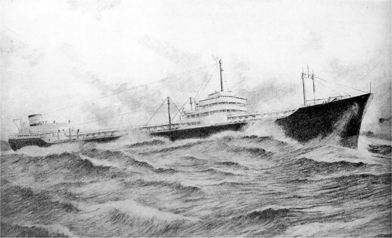 SIZE - POWER - STRENGTH
Striking conception of Esso's 628' super tankers, now under construction.
Accommodations
All officers will be berthed in the midship superstructure and petty officers and crew in the poop. Accommodations for Captain and Chief Engineer will consist of suites containing stateroom, ofiice and private shower and toilet. Other licensed officers, and Purser, Steward and Radio Operator, will each have a stateroom with private shower and toilet. An officers' recreation room will be provided in the midship house, while the officers' mess will be con-veniently located in the poop, petty officers and crew will be berthed generally not more than two persons per room, with either a private shower and toilet or connecting shower and toilet for adjoining rooms. There will be separate petty officers' and crew's messrooms and a comfortable recreation room for both. An engineers' dayroom, hospital, laundry and usual ship's service rooms will be provided. The galley will be electrically equipped.
Accommodations on the bridge deck will be provided for four passengers in two rooms, each with a private shower and toilet. The accommodations throughout will be of fireproof construction and mechanically ventilated.
The fire fighting and safety appliances provided will be of the usual high standard existing in Esso fleet tankers. Four 24-foot, 35-person metal lifeboats, two aft and two amidships, will be part of each vessel's lifesaving equipment. The boats will be suspended from mechanical davits.
Machinery
The propelling machinery will consist of a geared turbine propulsion unit with cross-compound impulse type steam turbines and a double reduction gear. The cross-compound turbines consist of one high pressure ahead turbine and one low pressure ahead turbine with an astern turbine incorporated in the exhaust end of the low pressure turbine. Multiple hand operated valves are used for control of the number of the first stage ahead nozzles to obtain improved steam economy for part load operation.
Reduction Gears
The two turbine rotors are connected to the high speed pinions through flexible couplings of the high speed gear tooth type. The double reduction gear has the high speed first reduction elements placed forward of, and above, the low speed reduction element. The two high speed pinions drive two intermediate gears, connected through a flexible coupling to a low speed pinion. The two low speed pinions drive the low speed gear. Double helix design is used for all the reduction gear elements. The main thrust bearing, housed in the forward end of the reduction gear casing, is of the pivoted segmental, single collar, marine type, and is arranged to take the thrust in both directions. The ahead
power and RPM for the unit are:
The propelling machinery is designed for reliable and economical operation at an estimated fuel consumption of .52 pounds of bunker fuel oil per shaft horsepower per hour when developing about 12,500 S.H.P. and not heating car-go, ballasting or tank cleaning.
The turbines are designed to operate at normal steam condition of:
Boilers and Condensers
Two Babcock & Wilcox watertube two-drum air incased boilers will be located on a fiat aft of the main propulsion unit. Each boiler will have furnace water walls, convection type superheater, desuperheater, economizer, air heater, mechanical atomizing oil burners, smoke indicator, air operated feed water regulators, combustion control, air puff type soot blowers and other accessories required for economical operation.
There will be a main condenser serving the main propulsion unit and turbo generators, and capable of maintaining a vacuum of 28.25" Hg, located under the main low pressure turbine. An auxiliary condenser is provided to condense the exhaust steam from the two turbo generators, cargo pump turbines and other steam actuated auxiliary machinery units. The auxiliary machinery which has been arranged to ensure reliable and economical operation includes three steam turbine actuated rotary feed pumps, main and auxiliary circulating and condensate pumps, main and auxiliary condenser air ejectors, lubricating oil service pumps in association with a gravity type lubricating oil system for the
main propelling machinery, a steam turbine actuated fire and Butterworth pump A'ith heater and drain cooler, a reci-procating general service steam piston type bilge and ballast pump, an electric motor actuated centrifugal fire pump, sanitary pump, two wash water pumps, two drinking water pumps, two Freon refrigerating machinery units, complete with condensers and cooling water pump, and engine room bilge pump, reciprocating type.
The feed heating system will be provided with four stages of feed water heating including a deaerating feed water heater. The evaporating plant will include two salt water evaporators and one make up feed evaporator and two distillers.
The boiler forced draft system will include two electric blowers equipped with vane control. Each boiler will have four fuel oil burners, served by two fuel oil service pumps and heaters in conjunction with Bailey combustion control equipment. Air puff type automatic control boiler soot blowers will be supplied with air from two large air compres-sors; a small compressor will furnish air to the combustion control system and feed water regulators.
Electrical Installations
The electrical installation will include two 400 K.W., 450 Volt, 60 Cycle, 3 Phase, A.C., steam turbine generators on a flat at the starboard side of the engine room.
These generators will operate on a steam condition, same as that of the main propulsion turbines. In addition, there will be transformers for the lighting services and galley ranges and two motor generators for supplying direct current service. A 60 K.W. Diesel generator, 450 Volts, A.C. current, will be provided for emergency lighting services and for use with the boiler cold starting system, having emergency forced draft blower, fuel oil service pump and feed pump.
A lathe, drill press and grinder will be provided in the workshop which is located aft on the boiler flar.
The deck machinery will include an electro-hydraulic steering gear of the two ram type, a steam windlass and five steam winches.
The engine and boiler room will be ventilated by eight supply and exhaust propeller type fans located in the ventila-tors.
Pumping Equipment
The cargo pumproom located between the aftermost cargo tank and the engine room will contain four twostage cen-trifugal cargo pumps, driven by steam turbines located in the engine room; these four pumps will be capable of dis-charging about 22,000 barrels per hour of 30 degree A.P.I., crude oil. Also in the main pumproom will be two steam reci-procating stripper pumps, and one rotary type stripper pump driven by an electric motor located in the engine room; each stripping pump has a capacity of 1,000 barrels per hour against a discharge pressure of 125 pounds per square inch at the pump. In the main cargo tanks there will be four 14" O.D. fore and aft cargo suction lines and a 6" stripping line which is connected into one of the main cargo lines in # 1 tank.
The stripping pumps are arranged to take suction from the vapor space of the main cargo pumps, the main lines, stripper line or sea, and discharge into #10 center tank, the main suction and discharge crossovers in the pump-room and to a 6" discharge line crossover on the upper deck. The four main cargo pumps are arranged to dischar-ge to four crossovers located on the upper deck aft of the amidship house.
A steam actuated reciprocating bilge ballast pump and a like type fuel oil transfer pump, with the customary suction and discharge connections, are to be provided in the forward pumproom.
The cargo piping and cargo tank venting system are arranged to permit the carriage of Grade "A" petroleum pro-ducts.
The aids to navigation include radio receiver and transmitters, radio direction finder, radar, echo sounding equip-ment, gyro compass and gyro pilot automatic steering.
Source : PACIFIC MARINE REVIEW, VOLUME 45, JUNE 1948
|