Auke Visser's International Esso Tankers site | home
First American Arcform Tankers - Part-3
Source : Marine Pacific Review, Volume 33, January, 1936.
Ventilation by natural draft is provided for all engine room and fire room space. For the cargo pump room an Ilg, electric motor driven exhauster is located in the pumproom deck house. This exhauster has a capacity of 1200 cubic feet of free air per minute and will draw air from the space under the pump-room gratings and discharge into the atmosphere.
All piping, fittings. valves, and surfaces of main and auxiliary machinery subjected to temperature in excess of 130 degrees Fahrenheit will be so insulated that the surface temperature will not exceed 130 degrees Fahrenheit when the ambient temperature is 100 degrees Fahrenheit. lnsulating material to he used is Rockwool for the boiler casings; 85 per cent Magnesia composition for all other surfaces under 600 degrees Fahrenheit; and Superex, or a combination of Superex and 85 per cent Magnesia for temperatures 600 degrees Fahrenheit or over. Insulation for piping to be of sectional type, covered with canvas or asbestos cloth. Insulation for flat or large curved surfaces to be in block form finished with hard finish asbestos cement.
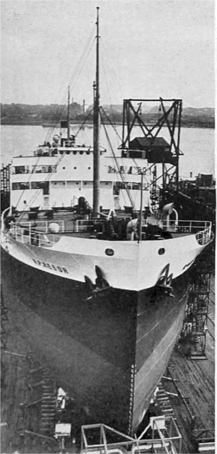 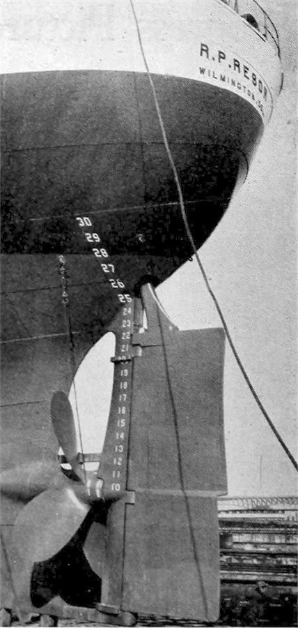 Right and left are bow and stern views of the tanker on the ways ready for launching.
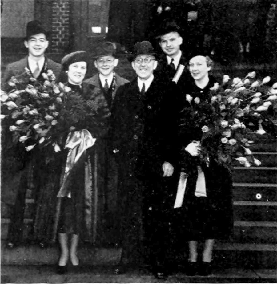 Above: Mr. and Mrs. R. P. Resor and family. R. P., now treasurer of the Standard Oil Company of New Jersey, has been 46 years in Standard Qil Service, working up from office boy, through the accounting and auditing departments.
Stern Frame and Rudder
One of the features given special attention when planning the tankers R. P. Resor and T. C. McCobb, was the design of the stern frame and rudder from the standpoint of obtaining the maximum propulsive efficiency, the best possible steering and inaneuvering qualities, and low rudder torque.
After a thorough series of model basin tests with different types of streamline rudders, and various combinations of Contrapropellers, the design shown in the accompanying illustration, and known as the Contra-Guide Rudder was adopted.
Although the Contra-Guide Rudder has been installed on a number of ships in service, including the Waterman Steamship Company's vessels Topa Topa, Antinous and Hastings, these tankers are the first in stallzitions of this type of rudder in new vessels in the United States.
The nornal type of Contrarudder is the combination of the fixed Contrapropeller, which is attached to the rudder post, and a symmetrical streamline rudder. Its object is to take the rotary motion out of the propeller jet and deflect the water aft in a straight rearward direction.
This results in increased speed for the same shaft horsepower, or if the speed is kept constant, a corresponding decrease in shaft horsepower or fuel consumption. Additional advantages are better steering and maneuvering and decreased rudder torque.
In the Contra-Guide Rudder the rudder itself, as well as the Contrapropeller is given a curved surface; the curvature being to port above the centerline of the shaft and to starboard below the centerline. ln this way the entire arrangement including the rudder acts as a Contrapropeller and thus the effective Contrapropeller Area is considerably increased over that of the normal type Contrarudder.
The table herewith summarizing the results of a Model Basin test with a vessel 406.8 feet x 54 feet x 23.5 feet, shows the improvement resulting from the normal Contrarudder and Contra-Guide Rudder , as compared with the normal single plate rudder.
S.H.P. Percent Saving
At the designed speed, 11 knots, the normal Contrarudder showed a saving in shaft horsepower of 15 percent, while the Contra-Guide Rudder indicated a gain of 19.2 per cent. A comparison of rudder torques for the same model shows:
Side pressure 1100 grams
It will be noted that for a given side pressure, the torque with the Contrarudder was 43 per cent less than with the Plate Rudder, and
with the Contra-Guide Rudder, there was a reduction of 58 per cent.
This comparison also shows that for angles of helm of 13.5 degrees and 14.5 degrees, respectively, for a Contra-Guide Rudder and Contrarudder, the steering effect is equal to that obtained with an angle of helm of 20 degrees for a Plate Rudder. Maintaining a course with minimum helm helps to increase the speed of the vessel.
Another test recently made with the model of a 500 foot tanker in one of the leading experimental basins with a Contra-Guide Rudder, gave the highest propulsive efficiency ever obtained in that basin.
In regard to the construction of the Contra-Guide Rudder fitted to the R. P. Resor and to the T. C. McCobb, it can be said that the design and workmanship is in keeping with the soundness and thoroughness of the other parts of these tankers.
The Contrapropeller, which also serves as the rudder post, is a steel casting in one piece, riveted through two flanges to corresponding flanges which are a part of the stern frame. No portion of the Contrapropeller or stern frame need be disturbed when
unshipping or shipping the screw propeller.
The rudder consists of a cast steel frame to which is electrically welded the side plates. Three large pintles are used.
Steam Generating Units
The steam generating equipment of the tankers is quite novel insofar as marine engineering is concerned.
This applies to the design, location and construction of the boiler units. The steam generators are of the D type, two per ship, set in battery with a single steel casing. The boiler position is far aft above the engine room which results in entire elimination of uptakes, the stack connecting directly to the discharge casing just above the air preheater outlet.
The boiler drums are of fusion welded construction no rivets being used. The design was developed to meet the specific conditions of cornpactness, lightness and space limitations prevailing in that particular part of the vessel.
To be continued on Part-4
|
See also : First American Arcform Tankers - Part-4