Auke Visser's International Esso Tankers site | home
First American Arcform Tankers - Part-4
Source : Marine Pacific Review, Volume 33, January, 1936.
 Sectional elevation of Foster Wheeler steam generator and model of unit casing for two boilers as installed on Tanker R.P. Resor.
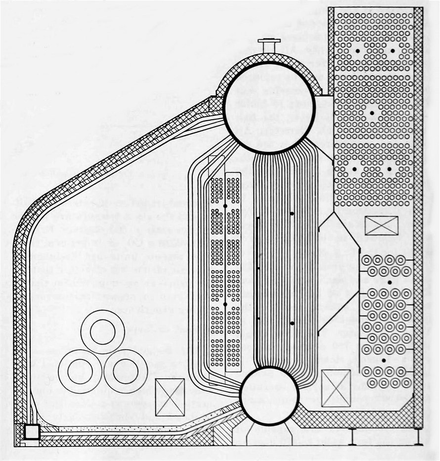 The two steam generators are of Foster Wheeler design and construction and are composed of two drums, the steam drum being placed directly above the water drum and connected to it by banks of vertical tubes. The tubes are so arranged that space is left between the third and fourth rows from the fire for the installation of a convection superheater. A steel baffle provides two gas passes through the boiler heating surface, the gases then flowing through an economizer of the extended surface, cast iron, armored marine type. Final heat recovery is effected through the use of a tubular air preheater. The boiler, superheater, economizer and air preheater are fitted with steam soot blowers. Desuperheaters and feed water regulators are installed.
The furnace is of D shape with water cooling tubes in the floor, front wall and roof. Firing is through three oil burners placed in one side wall of the furnace. This arrangement gives ample refractory with which to maintain a sufficiently hot furnace for rapid combustion, yet insures cool floor plates and substantial front wall and roof construction without thick, heavy refractory.
Placing two such boilers in a steel encased battery, with the economizers and air preheaters adjacent at the center of the ship and the furnaces toward the sides of the vessel, gives maximum compactness without sacrificing accessibility. All air preheater and economizer tubes are of 2-inch diameter and may be replaced individually without removing any of the tubes. All fire rows of boiler
tubes are 2-inch diameter, the bal- ance being 11/4-inch diameter. All boiler and economizer tubes are designed to allow for expansion without imposing undue stress upon the joints. The boiler drums are of Class I welded construction subjected to X-ray inspection by a 8000-volt machine. This is similar to the procedure followed in building welded drums for the U. S. Navy.
The operating pressure will be 430 pound gage and each unit will have 1830 square feet of heating surface including 780 square feet in the economizer and 1300 square feet in the air preheater. The final steam temperature is 750 degrees Fahrenheit and each stenm generator is capable of producing 13,000 pounds steam per hour at normal operation and 20.000 pounds per hour maximum.
The economizers are capable of raising the feed water to 370 degrees Fahrenheit before it enters the boiler and the stack temperature will be approximately 300 degrees Fahrenheit. With a CO2 of 14 per cent these new marine units are designed to give an efficiency of better than 87 per cent an accomplishment that is very rare in present marine engineering experience.
Soot Blowers
The boilers, economizers and airheaters installed are equipped with
Diamond "Automatic Valved Soot blowers, which require only one operation to open and cose the valve in head and simultaneously rotate the element.The automatic valved feature saves up in to 50 per cent of the steam used by an ordinary valve in
head blower, because the valve is open only while the element is rotating.
These soot blowers provide any required blowing arc up to and including 360 degrees. Blowing is either clockwise or counter clockwise according to the gas flow. Full or partial blowing pressure can be applied at any point of the arc; this exclusive feature protects baffles and brickwork and also saves steam. The goose neck design of the head provides unrestricted steam flow with
minimum pressure drop. Positive valve closing is assured by the cam and trigger action, another exclusive feature.
Calorized and Dialoy elements assure long life. Experience has proved the poppet type valve to be the only satisfactory valve for this difficult service. Seat, disc and stem are forged monel metal; seat and disc are readily accessible for regrinding without demounting head.
Propulsion Turbines
The Allis-Chalmers cross-compound propulsion turbines built for these ships were designed for normal steam conditions of 375 pounds gage pressure, 725 degrees Fahrenheit total temperature and 28 1/2 inches vacuum. For normal power of 3000 shaft horsepower at 90 revolutions per minute and an attached generator load of 125 kilowatts, the turbine unit delivers 3249 horsepower at the turbine couplings. For maximum power of 3300 shaft horsepower at 93 revolutions per minute and an attached generator load of 13-5 kilowatts, the turbine unit delivers 3568 horsepower at the turbine couplings.
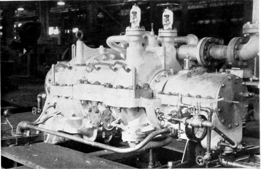 Above: The high pressure casing.
In general the design of the tur- bines follows standard Allis-Chalmers impulse-reaction turbine design with certain modifications as required for marine applications. Simplicity of design and accessibility without sacrificing efficiency were the yardsticks used by the designers.
The high pressure turbine is of the impulse-reaction type, the rotating element consisting of one 2 row velocity impulse stage followed by 17 rows of reaction blading. The low pressure turbine is of the straight reaction type with ll stages of reaction blading. Both the high pressure and the low pressure spindles are of the solid forged design with integral bearing shafts.
The blading used in these turbines is of standard Allis-Chalmers design. All impulse blades are milled all over from stainless steel bar stock. Proper spacing of the impulse blades is obtained by thickening the blade root instead of using individual spacer pieces. The reaction blading is made up in sections which are assembled in the blade grooves. The individual reaction blades are cut
from carbon chrome nickel steel stock rolled to the exact blade shape.
The blade sections are formed by holding the individual blades in jigs and silver soldering the shroud ring in place and casting on the foundation ring. This procedure insures accurate blade spacing and angularity. The use of blade sections which are accurately balanced before being assembled in the turbine insures a good running balance.
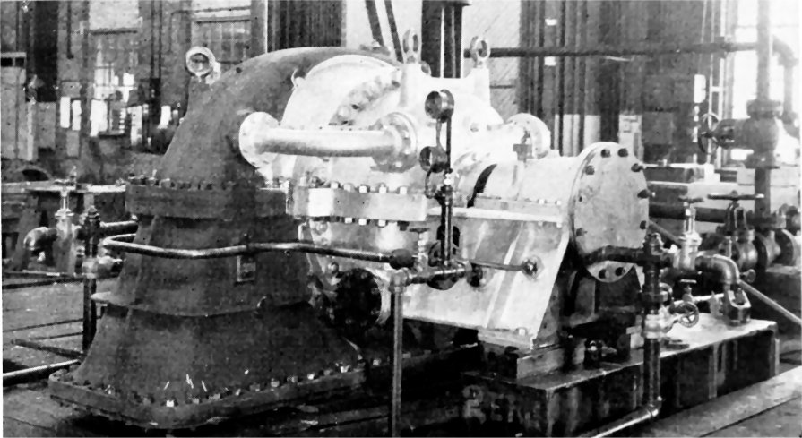 Above: The low pressure casing Allis-Chalmers main propulsion turbines.
The designs of the turbine cylinders are simple and symmetrical and introduce certain features which are new to the marine field. The high temperature steam for both the high pressure turbine and the astern turbine is confined to the relatively small nozzle chests which are cast separate and welded into the cylinder shell. This means that the turbine cylinders are protected from the high temperature steam and that excessive cylinder distortions which would be obtained with the conventional marine design are eliminated.
Steam admission to the turbines up to approximately two-thirds normal flow is controlled by the ahead turbine throttle valve. From two-thirds to maximum load the flow of steam to the high pressure turbine can be adjusted by means of two hand operated valves, located on bop of the high pressure cylinder. Flexibility in the steam connection to the high pressure cylinder is provided by a novel compact inlet piping arrangement welded directly to the turbine cylinder.
The combined journal and Kingsbury thrust bearing used on each turbine spindle, while new to the marine field, is a standard Allis-Chalmers design that has been very successful.
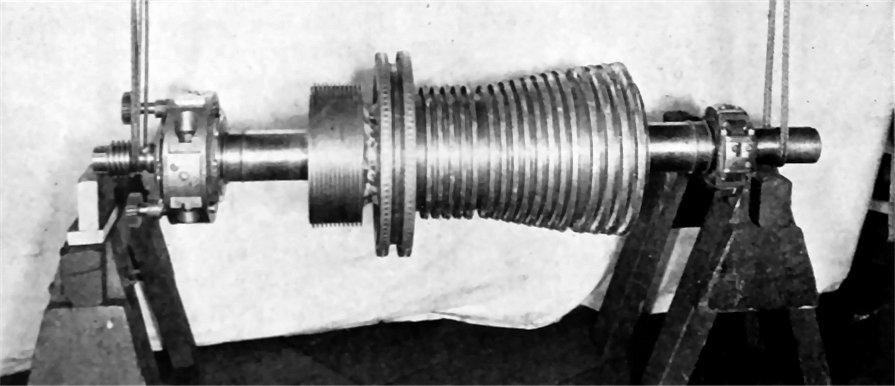 High and low pressure (below) spindles of Allis-Chalmers main propulsion turbines.
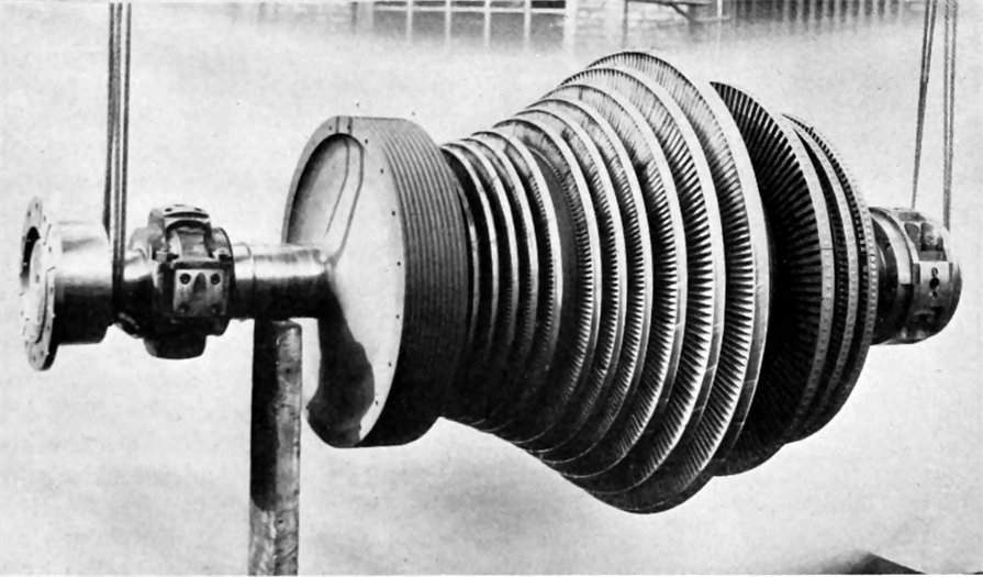 The turbines are provided with two extraction nozzles in the high pressure turbine and one extraction nozzle in the low pressure turbine to furnish steam for the evaporator, the heating system, fuel oil heating, and feedwater heating. Shaft packing glands on both turbines are of the Huhn carbon ring type. The turbines were provided with a governor oil pump which furnishes oil under a
pressure proportional to the turbine speed for use on a maximum speed governor valve.
To be continued on Part-5
|
See also : First American Arcform Tankers - Part-5