Auke Visser's MOBIL Tankers & Tugs Site | home
Successful Sea Trials of Socony-Vacuum Tanker "MOBILGAS"
De Laval Geared Turbines Satisfactorily Pass All Tests
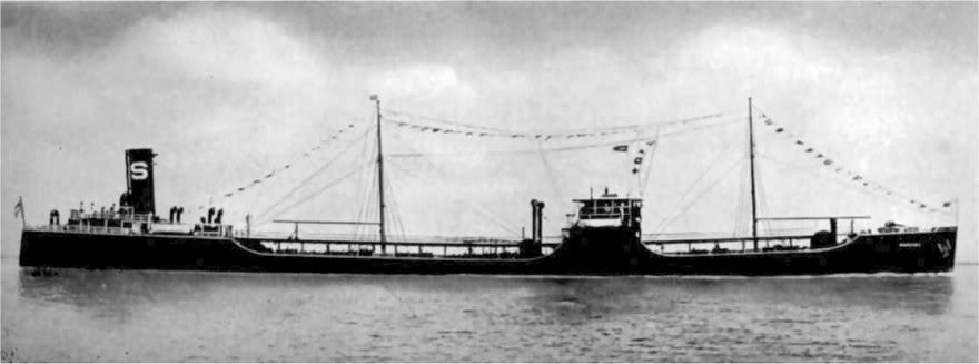 SS. Mobilgas.
In April, 1936, Pacific Marine Review carried a full illustrated description of four sister tankers then building at the Sun Shipbuilding and Dry Dock Company for the Socony-Vacuum Oil Corporation and the Pan-American Petroleum and Transport Company, under the direction and to the designs of N. J. Pluymert, naval architect, of Socony-Vacuum Oil Corporation. The power plants on all four ships are identical.
The two ships for Socony-Vacuum, named respectively MIobilgas and Mobiloil, have been delivered after very satisfactory trial trips. In this article we are recording the results for the Mobilgas, which ran her sea trials on February 9 and was delivered on February 11.
Principal dimensions of this vessel at time of trial trip were:
Her propulsion power plant consists of 2 Foster- Wheeler three drum, bent tube, type A steam generators, which are designed to produce steam at 450 pounds pressure and 720 deg. F. temperature at the superheater outlet. This steam is delivered to a cross-compound double reduction geared De Laval turbine designed for a normal rating of 4000 horsepower when receiving steam at 375 pounds pressure (gage) and 700 deg. F. total temperature, and when exhausting to a vacuum of 28 % inches. The unit is designed to carry a 10 per cent overload continuously. This turbine must also operate satisfactorily with steam at 375 pounds pressure at temperatures down to 585 deg. F. At full load the high pressure turbine rotor turns 5480 revolutions per minute.
The propeller is of the four-bladed built up type, with semi-steel hub and manganese bronze blades of streamline section with variable pitch, designed to absorb 4000 horsepower at 75 revolutions a minute, and drive the hull at a sustained speed of 13 knots. This propeller has a tip diameter of 19 feet, 8 inches, a pitch of 18 feet, 4 inches, and 104 square feet of projected blade area.
 Main propulsion gear.
That the turbines, propeller, and hull lines of this ship were designed truly for the specified performance is graphically shown by the results. The Mobilgas, properly trimmed, and down to her marks on full loaded displacement, ran 13.8 knots at 80.5 r.p m. propeller speed and with the turbine generating 4100 shaft horsepower.
Her fuel consumption works out at approximately 0.6 pounds of oil per brake horsepower hour.
The power plant is described in detail as follows:
The high pressure turbine is equipped with eleven pressure stages, the first of which contains two rows of moving buckets, while the remaining ten are single impulse wheels. The low pressure turbine has seven pressure stages, all of the single impulse type. The astern turbine, which is enclosed in the same casing with the low pressure turbine, has two pressure stages, each consisting of one wheel with two rows of buckets.
The turbine rotors are of the so-called "built-up" type; the high pressure rotor and part of the low pressure rotor con-sist of turbine discs shrunk on the turbine shafts, the low pressure rotor being built in three sections bolted together. This construction permits easy access to any individual wheel should any accident occur necessitating overhaul of the turbine.
All turbine wheels are made from heat-treated nickel steel forgings. The turbine wheels are each statically and dynamically balanced and the complete rotors are also subjected to static and dynamic balance in balancing machines prior to assembly in the turbine. The shaft and rotor are designed with their calculated first critical speed not less than 35 per cent above normal operating speed.
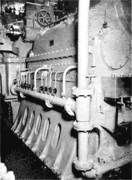
 Turbine-driven boiler feed pump on the Mobilgas. The power plants of four tankers built
by Sun in Chester are identical.
All stresses in the revolving element, that is, stresses in turbine wheels, turbine buckets, and bucket fastenings, are very conservative, and will not exceed onethird of the elastic limit of the material used when operating at 10 per cent above normal speed. The turbine rotors are held in axial position by Kingsbury bearings located in separate housings and provided with means for checking running clearances.
The casings of both the high and low pressure turbines are made of steel. The steam chest of the high pressure turbine is incorporated in the casing, but the steam chest of the reversing turbine is a steel casting located inside, but independent of, the low pressure casing, to allow for difference in expansion between the steam chest in contact with boiler steam and the casing in contact with steam at exhaust pressure. All steam passages are carefully streamlined.
A group of guide vanes placed between the ahead and astern turbines in the low pressure casing, prevents im-pingement of steam exhausted from one turbine upon the buckets of the other and insures uniform distribution
of steam over the condenser, which is located athwartship underneath the low pressure turbine.
There is a connection on the turbine casing for the extraction of 2500 lb. per hr. of steam at 35 lb. gage for use in feed heaters and for other ship purposes.
The as
tern turbine is designed to develop not less than 75 per cent of the full ahead power for continuous operation, and 100 per cent of normal ahead torque at one-half of normal ahead propeller speed.
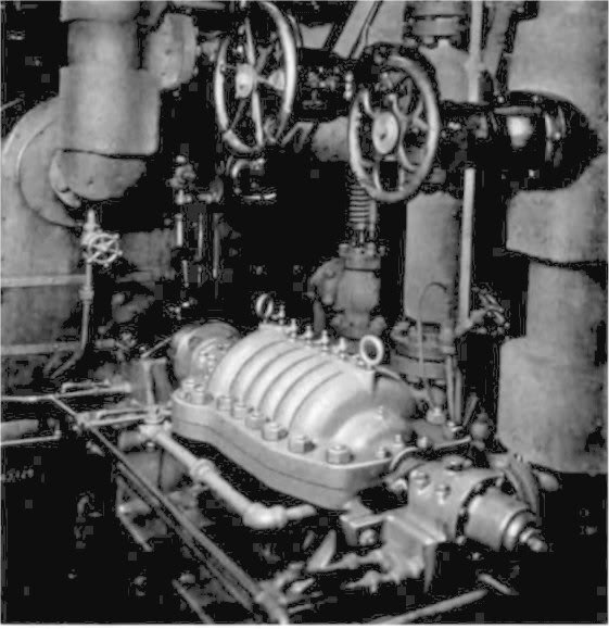
The control valves include a valve for ahead operation, a valve for astern operation, and a guarding valve to assure against leakage through the latter. A regulating valve, placed ahead of the main throttle valve, is operated from a hydraulic governor driven from the high pressure turbine shaft and is adjustable to hold any speed from one-half of normal speed to full speed, and also arranged to close in the event of failure of lubricating oil pressure. There are, in addition, three hand valves for nozzle groups, so arranged that with the throttle valve full open various combinations of nozzles can be used to vary the power in small increments from 50 per cent of rated load to 10 per cent overload, thus making efficient operation possible at reduced speeds. All valves have steel bodies, with stainless steel trim.
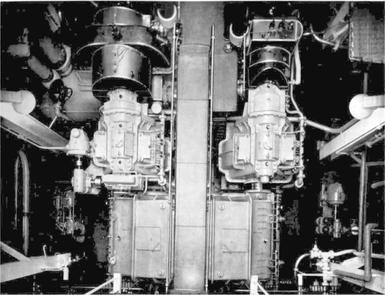 Looking down on the De Laval compound turbine and double reduction gears of the Mobilgas.
The gears are of the double helical type with the two high speed gears and the double pinion low speed gear built in three separate casings.
The pinions of the low speed gear are supported by three bearings.
The turbine shafts are connected to the first gear reduction pinion and the pinions of the second reduction gears are connected to the gears of the first reduction gears by flexible couplings.
The tooth loading of the gears is conservative to in-sure long operating life.
The gear centers are of cast iron, shrunk and keyed on the shafts, while the rims are of annealed forged steel, shrunk and pinned on the centers.
The turbines and gears were tested at the De Laval test-room under full steam pressure and temperature, and to 15 per cent above the maximum operating speed before shipment.
In addition to the main propelling units, the ship is equipped with the following auxiliaries of De Laval manufacture:
Three six-stage turbine driven boiler feed pumps.
Main and auxiliary condenser circulating pumps, the main circulating pump being driven by a De Laval geared turbine.
Main and auxiliary condensate pumps.
Turbine driven fire pump.
Centrifugal sanitary pump.
Geared turbine to drive the general service pump.
Two De Laval-IMO lubricating oil pumps and a De Laval centrifugal oil purifier.
Source : PACIFIC MARINE REVIEW, Volume 34, MAY. 1937
|